A Breakdown of the Components
Preassembled Pump Stand
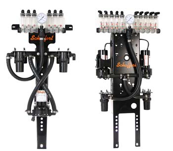
GX1 SINGLE PUMP & GX2 DOUBLE PUMP DISTRIBUTION CENTERS
Depending upon the size of the implement and the desired rate of application, systems can be either single or dual pump and are shipped 90% assembled.
The pump stand is predrilled for attachment to the implement bars or tongue (optional mount bracket required). Either system consists of the stand, pump(s), filters and manifold distribution components. Both systems are provided with two filters.
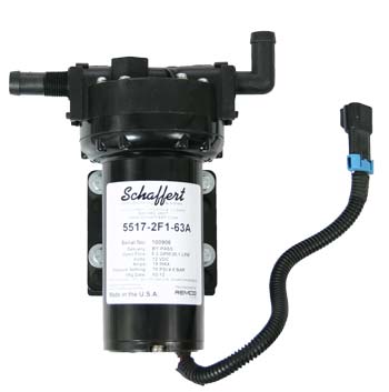
REMCO PUMP
The Schaffert Fertilizer Distribution System is powered by an American made, 12 volt REMCO pump.
The heavy duty motor is sealed with epoxy coating to resist fertilizer and chemical exposure. The pump has a five chamber construction that will handle up to 300 gallons per hour or 5.3 gallons of liquid per minute.
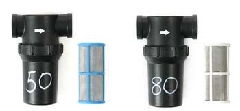
FILTERS
Fertilizer should enter the system through the 50 mesh filter housing, run through the pump(s) and proceed to the 80 mesh filter housing for discharge to the manifold. These caged filters are placed in directional housings.
Upon exiting the 80 mesh filter, the fertilizer is directed to the manifold distribution component.
The customer will need to reattach the manifold assembly to the main stand and connect the flow hose to the manifold. These three connections will complete the assembly of the pump(s) stand. (See Manifold Distribution Component.)
Electrical Connections
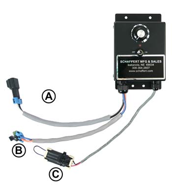
Wire connections (see image):
A: 12 Volt DC—Power connection to battery ONLY
B: Pump Cable Connection and/or “Y” Cable—Connection for dual pump systems
C: Remote Run Hold Whisker Switch Connection—DO NOT discard shorting plug after removal; retain for use should Run Hold switch get damaged
MANX CONNECTIONS
We have had a special 12volt/25 amp speed controller designed. The Man-X Controller will handle the load of a single pump or two 12 volt pumps simultaneously for the larger planters and drills on the market.
On the front of the Man-X Controller is the main on/off switch plus a control knob used to increase or decrease motor speed, thereby changing the pressure within the system.
The preferred installation of the Man-X Controller is in the cab of the tractor with the provided fused power cable connected to the tractor battery and NOT to an accessory plug. This method allows for the proper amperage draw by the motor(s).
Other connections to the Man-X Controller are for the power cable(s) to the pump(s) and the remotely mounted Run Hold Switch.
Should you have a system that requires dual pumps, a provided “Y” cable is plugged into the controller pump lead and the two pump power cables are plugged into the “Y” cable.
The main power switch of the Man-X controller is on the face of the unit.
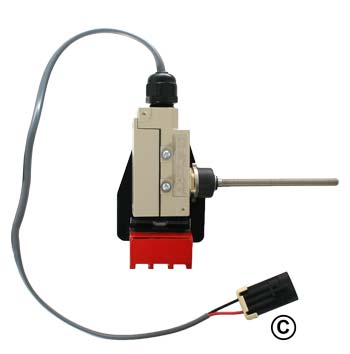
MAGMOUNT & RUN HOLD SWITCH
The Run Hold Switch and its magnetic mounted bracket (Magmount) also plug into the Man-X Controller. These connections are described in the instruction sheet included with the Man-X Controller.
The Run Hold switch and its magnetically mounted bracket is positioned near the lift arms of the 3 point hitch or the lift wheels of the planter. With the main power switch on and the Remote Run Hold switch connected, the pump(s) will operate when the planter is in the ground and off when lifted.
The whisker wire in the straight position (as shipped) is closed for normal operation. When the whisker is bent, power is interrupted and the pump(s) operation ceases.
The 100 pound pull magnet/bracket allows multiple positioning options for you to choose. We advise you tether the Magmount to your planter.
Manifold Distribution Component
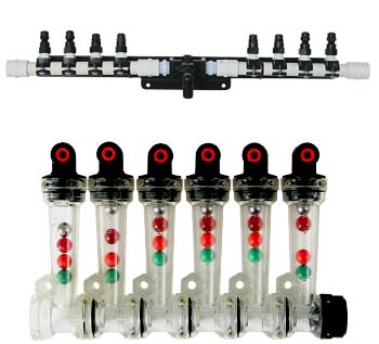
MANIFOLD OPTIONS
Two types of manifolds are offered to the customer.
Both the PVC piping system and the visual Wilger columns are designed to insure that equal amounts of product are provided to each row.
This is accomplished by placing the properly sized orifice in the top of each manifold outlet.
Orifice selection charts and installation guidelines are provided separately.
The individual row unit lines are either 1/4″ OD tubing (less than 10gpa) or 3/8″ OD tubing depending upon the customer application needs.
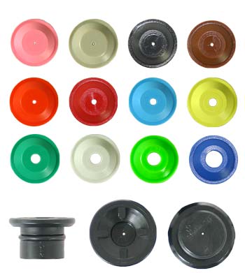
APPLICATION RATE
This pressure in combination with properly selected orifices, ground speed, fertilizer weight and row spacing will determine the rate of application.
With the rate chart provided with each system, one can select the proper pressure and orifice for the desired gallons per acre (gpa).
The type of orifice used will also depend on the chosen manifold setup. The colored disc orifices are used with the PVC manifold. The Wilger orifices are used with the Wilger columns.
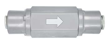
CHECK VALVES
A 5 pound check valve is provided for each line.
The check valve will close with loss of pressure from the pump(s) shutting off and liquid will remain in the system, keeping it fully charged until planting is resumed. A small amount of fertilizer will be lost from the check valve down to the row unit.
For this reason, it is advised that the valve be placed as near the discharge site as possible, but still remain accessible should difficulties arise.
The Check Valves are directional and connect in the same manner as the Quick Connects (see next).
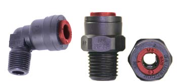
QUICK CONNECT
he tops of the manifold are terminated with a Quick Coupler (QC). This device makes it very easy to connect your line hoses.
These couplers act as a “Chinese Finger”, in that once the hoses are inserted they cannot be easily removed. HOWEVER, should you need to remove a hose, simply hold the ring of the coupler next to the body of the fitting with your fingernail or pocket knife. This will release the pressure against the hose. Then give a light pull on the hose for removal.
It is important that prior to inserting the hose into the QC, the hose have a square cut end, as it must seat against an O ring inside the coupler.
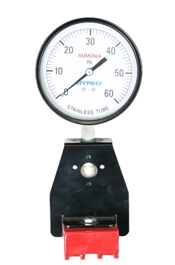
GAUGE
A 60 pound stainless steel gauge is included and may be mounted either directly on the manifold tee fitting or remotely, using a magnetic bracket.
Off-Season Care
Upon the completion of planting season, we highly recommend that the entire fertilizer distribution system be flushed out with clean water.
Fertilizer will eventually crystallize and can cause damage to components of the system if this step is ignored. Many customers will recharge and then drain the system prior to storage, and then store it with Recreational Vehicle (RV) antifreeze.
